Rapid erection technology for multi-level crossing bridges
(rapid erection method “QCIB method”)
Overview of the technology
The QCIB method refers to the rapid, safe, and economical construction of whole multi-level crossing bridge systems of superstructure-lower structure integrated structure, including foundations, for multi-level intersections in urban areas.
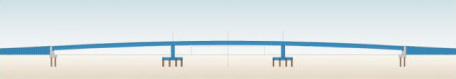
The bridge bodies are of superstructure-lower structure integrated rigid-frame structure, and the main girders, the bridge piers, and the footing are of steel block precast structure.
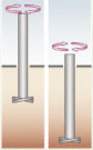
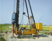
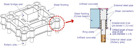
Rotary penetration steel pipe piles “wing piles,” which are piles equipped with a wing for improving end bearing force, are used for foundation piles. The joining method is the double pipe type pile head joint structure, which embeds the heads of the foundation piles directly into the steel footing.
The construction of the bridge body begins with the integral assembly of bridge girders on both sides, away from the intersection. Then, the center span girders are conveyed to the intersection on conveyance equipment, such as self-propelled carriers, and joined to the side span girders and steel footing.
Features of the QCIB method
-
The adoption of the superstructure-lower structure integrated structure for bridge bodies improves earthquake resistance, economy, and maintainability. In addition, single-post type steel bridge piers help ensure sufficient space for right turn lanes.
-
The bridge girders, piers, and footing are all of steel block precast structure and contribute to reducing the onsite assembly period.
-
Intersection girders can be erected in a short period of time with launching large block erection. This can considerably reduce the period of restricted traffic at the intersection concerned.
-
With the help of rotary piles, such as wing piles, used for foundation piles, construction work can be carried out without earth removal and with less noise and vibration.
-
The footing can be downsized and the construction work period can be reduced through the double pipe type pile head joint structure for rotary piles and steel footing.
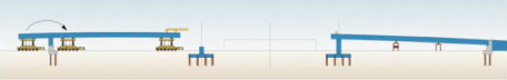
Construction work procedures by QCIB
STEP1

-
Drive rotary piles (wing piles, etc.) into the ground of the site.
-
Erect bridge piers P1 and P2 (steel footing, steel bridge pier) and bridge abutments A1 and A2.
-
After bridge abutment A1 has been completely erected, begin assembling the center span girder on the bents in the A1-side side span.
STEP2

-
The figure above shows the assembly of the center span girder almost completed.
-
After the completion of bridge pier P2, begin erecting the A2-side side span girder according to the steps described above.
-
Erect the A2-side side span girder and embank the A2-side simultaneously.
STEP3
-
Load the center span girders onto the transportation equipment (self-propelled carriers).
-
On the day before launching, move the center span girder to the intersection, and load it onto another piece of transportation equipment in the location of bridge abutment A1.
STEP4
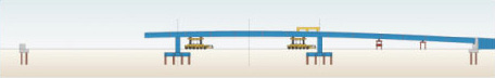
-
Complete launching large block erection of the center span girder overnight.
STEP5
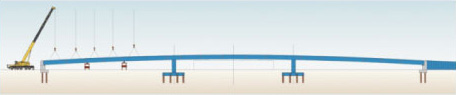
-
Erect the A1-side side girder.
STEP6
-
Perform embankment on the A1 side.
-
Construct the wall handrail, the medial strip, pavement, etc., and complete the construction work.
Overview
The QCIB method refers to the rapid, safe, and economical construction of whole multi-level crossing bridge systems of superstructure-lower structure integrated structure, including foundations, for multi-level intersections in urban areas. In this method, bridge bodies are assembled on both sides of an intersection, and center span girders are carried to the intersection on transportation equipment, such as self-propelled carriers, where they are joined to existing side span girders and steel bridge piers. The bridge bodies are of superstructure-lower structure integrated rigid-frame structure, and the main girders, the bridge piers, and the footing are of steel block precast structure. Rotary penetration steel pipe piles “wing piles,” which are piles equipped with a wing for improving end bearing force, are used for foundation piles. The joining method is the double pipe type pile head joint structure, which embeds the heads of the foundation piles directly into the steel footing.
Features
1.Cost reduction by high bearing force and rational design
The wing provided at the end of the pile can provide high bearing force.In addition, high horizontal bearing force is expected from a spread head pile, and costs can be reduced by rational design fit for the design conditions.
2.Totally free of earth removal
The QCIB method uses rotary propulsion, which can avoid earth removal or surplus soil.
Earth removal-free construction work can be achieved by using a three-point support type pile driver or full-perimeter rotary drill according to the construction conditions.
3.Environmentally friendly
This method generates less vibration and noise and is environmentally friendly because it does not use cement milk, etc.
Overview
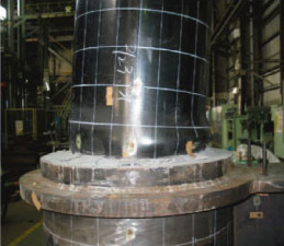
The steel footing is of grid integral with a bridge pier , which is divided into several blocks and assembled on site with bolts. This steel footing is equipped with the same number of pipes as the number of foundation piles, which is slightly larger than the diameter of the foundation piles. Install the steel footing so that the foundation piles can be inserted into the pipes, and fill the gaps between the pipes and the piles with concrete or another proper material to form rigid connections. The onsite formwork or reinforcing steel assembly work is no longer necessary, and it can reduce the construction work period as well as the period of restricted traffic .
The steel footing, which can be made smaller than the concrete footing, can reduce the volume of excavation and the area of traffic regulation and ensure sufficient space for right turn lanes.
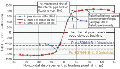
Horizontal withstanding load test of the double pipe type pile head joint structure
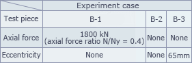
Test purpose
-
Check the load conveyance mechanism of the pile head joint under load during operation ( usual: seismic Level 1 ), and establish a design method for joints.
-
Check the deformation or breakage of the pile head joint until the end , and verify the safety of the structure.
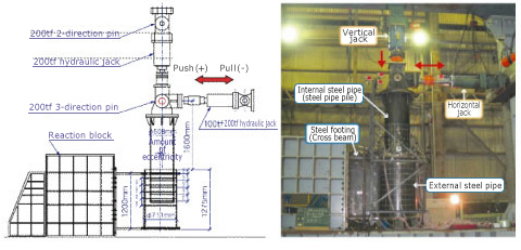
The following facts were confirmed in the test:
-
The proof stress of the joint exceeded that of the pile. Although the pile buckled, the infilled concrete was not damaged.
-
Regardless of whether the pile was eccentric, the pile head joint bore higher proof stress than the total load of the steel pipe.
-
Horizontal force and bending were transmitted to the external steel pipe via the bearing pressure of the concrete. Axial-direction compression and tension were conveyed via the shear connectors of the internal and external steel pipes and the adhesion of the concrete.
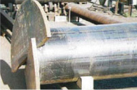
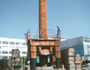
State of the pipe after the test
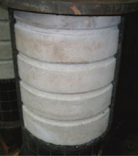
Comparison of envelopes between load-displacement hysteresis curves